Hey, I am just starting some jobs with the MK6 and I am trying to find some good cutting / filling configuartions for wood.
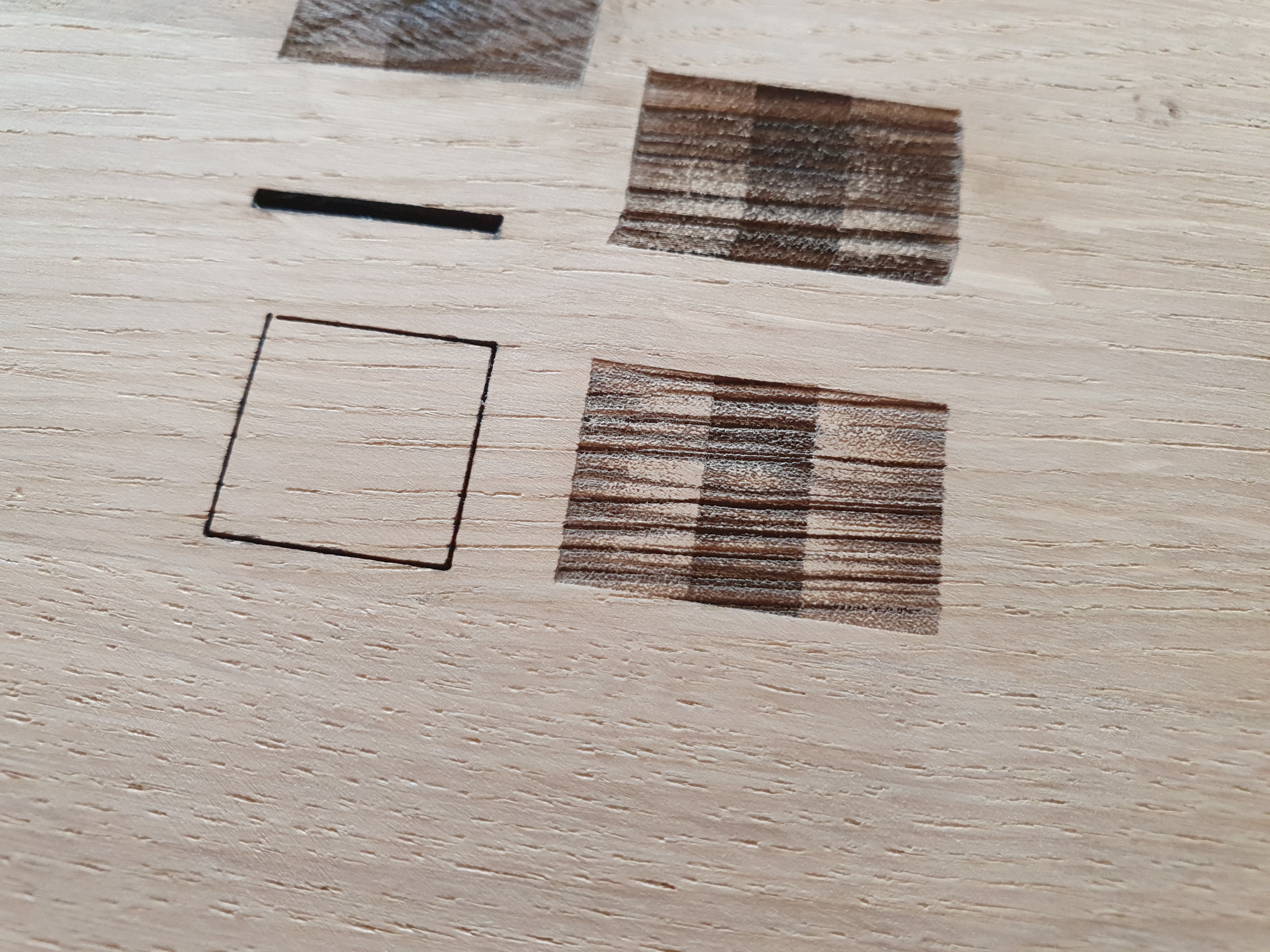
I tried some simple squares and I noticed that the filled square is way too wide (23mm instead of 15mm in the x-axis). If I run the job cutting the line only the square is just fine 15x15 (see picture)
Also: in the middle of the filled sqare there is always an area engraving deeper… has someone the same problem? How can I get rid of it? In general, the graving is not looking so smooth… any ideas on that too?
Thanks for any help here!
(PS: it appears always, so it doesn’t depend on the wood stucture…)
By engraving you actually have an offset Square.
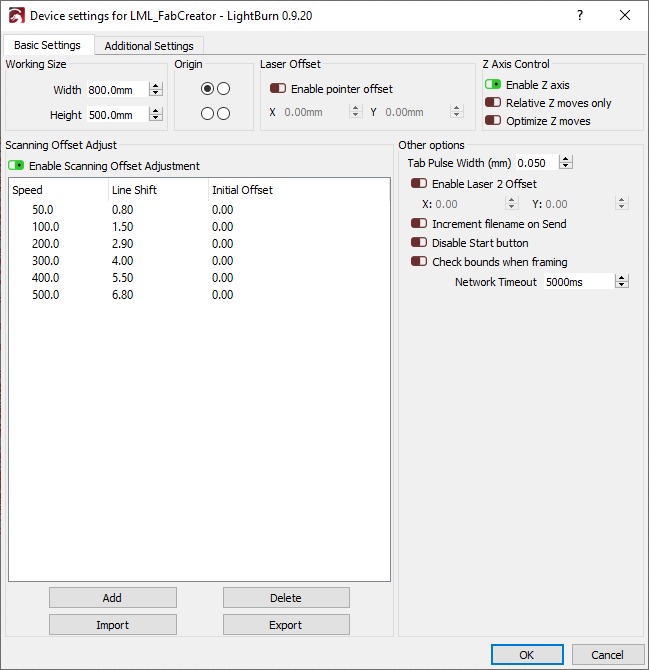
You need to set up the line shift in scanning offset adjustment.
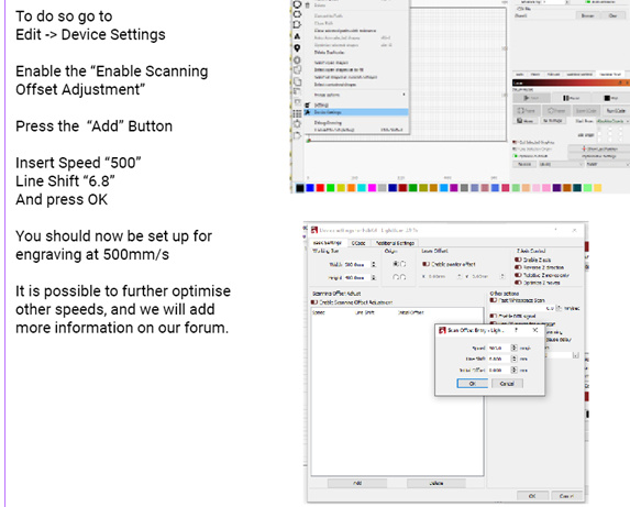
-Device settings
-Enable Scanning offset Adjustment,
Speed 500 – line shift – 6.8 Initial offset - 0
You have to find out for every speed the right offset value. I Can share later on our founded values with the mk6
Hey @cmachtel, thanks for this hint. But is this really the only option to deal with this problem? I have to enter every speed I want to use to and match that with an Offset adjustment? If so, would be great if you can help me out with your settings here… But what happens when I use a speed in between two entered offsets?
I was also reading something about the ‘PWM Rising Edge Valid’ in the Ruida Controller… might this be the solution? PWM Setting
@FabCreator Have you an idea about this toppic? I guess I am not the only one having this problem, as I have not changed anything about the controller settings you have defined for the MK6. Any suggestions on that? Thanks!
With raster engraving it is necessary to find these values as it need to compensate for the laser turning on. we found the value for 500mm/s and tend to just engrave at this speed.
The values should be pretty much identical for every machine so @cmachtel values should work with yours.
We are looking into an issue of what would appear to be lost steps. somthing which is not possible with closed looped motors found in the FabKit/CorePlus.
We opted for these motor on recommendation from a friend who uses them in a metal 3D printer. They discovered a slippage on the pulley could occur when accelerating/changing direction quickly. You cannot feel it when testing for blacklash as you need the sudden torque of the motor to create the slip.
We currently dont have a FabKit/CorePlus, more to assemble next week. Once i confirm thats whats happening it should be an easy fix with a bit of loctite but it does explain why it only seems to lose precision when doing lots of small repetitive vector engraving
An option for the moment can be to reduce the acceleration.
The PWM value should be correctly set as its not a skew you are seeing but a ghosted image which is to do with either backlash problems or the delay DC CO2 lasers have.
Alright then. I will test the settings and do some filling tests and adjust the offset. What is actually the recommended maximum speed of the x and y axis? 500mm/sec is quite high for my understanding…
Are there also some other basic settings I have to configure and think about?
And one quike unrelated question: Is it possible to adjust the zero/zero point in lightbrun to the point in the machine where my material has its zer/zero point? Otherwise I always have to add the offest between the home piont of the machine with the offest where the material starts…
500mm/s is fine for rasting. (Fill) Thats when the x axis moves left and right quickly and the laser pulses to create your image for vectoring speeds it should be a lot slower than 500mm/s. As the laser tube is being moved you have more mass so id recommend a speed around 50mm/s.
in lightburn you can change where you start your job, absolute coordinates or user origin.
absolute coordinates will always start from the home point. User origin allows you to jog to where you would like to start the job. Click origin on the machine and that will become the start point.
FabKit-Core+ v3.zip (1.5 KB)
The error over long detailed jobs may have indeed been because the PWM was incorrect.
Give these settings ago, make sure to save your existing ones in LightBurn before you copy these over just incase you want to revert
@FabCreator thanks for the info. So changing the PWM did solve the problem? I will give it a try then.
@cmachtel Thanks for the values! I will check them with my findings. I have also read that lightburn calculates the values for speed that are not in the table from the data you proivde. So in your case for a speed of 250mm/sec lightburn calculates the line shift from the other values… but i have not tested it yet.
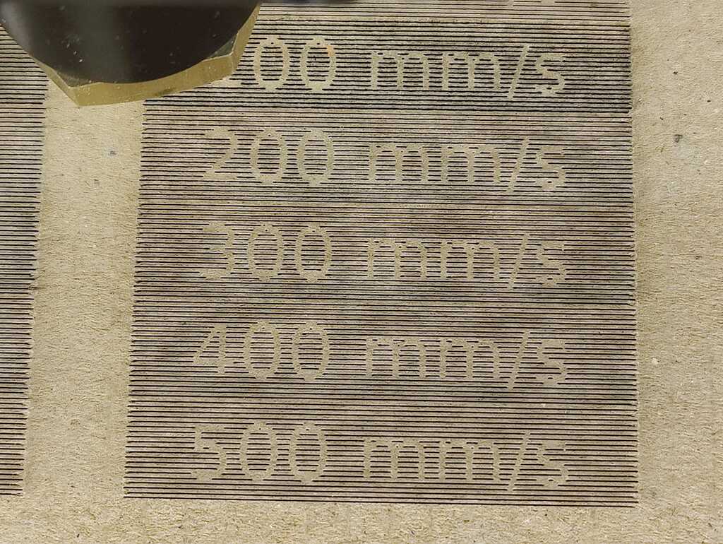
As a follow-up and for future reference, I had to tweak a bit more (see the pictures of before and after). My line shifts are:
speed
line shift
initial offset
100 mm/s
1.475
0.00
200 mm/s
2.825
0.00
300 mm/s
4.150
0.00
400 mm/s
5.450
0.00
500 mm/s
6.750
0.00
I found these by trial and error and adjusting a tiny bit more or a tiny bit less
(using cardboard for testing). I also attached the lightburn file I used.
Thanks a lot egeltje for the file. Got mine tweaked now. I’m not sure, but it seems to matter what type of machine it is, as I need less than half the values that you got.
For FabCore:
speed
line shift
initial offset
100 mm/s
0.55
0.00
200 mm/s
1.2
0.00
300 mm/s
1.8
0.00
400 mm/s
2.35
0.00
500 mm/s
2.9
0.00
I also had to fill nearly 2 sides of a cardboard until I found the sweet spot. I also had to rise the power of the laser for better visibility on the faster speeds.
hope this helps someone.
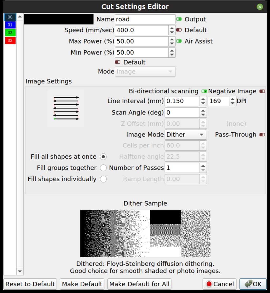
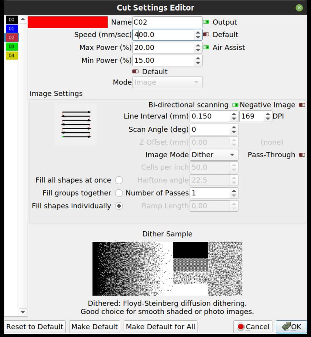
Hmmm. Seems that the line shift works great for engraving lines (vectors), but not so much for images in lightburn (0.9.24 on linux). More tweaking ahead…
Bi-directional vector rastering is no problem after setting the line shift, but bi-directional image rastering still gives a (small 5mm) shift. And the image rastering is shifted relative to a vector cut in the same job. Will investigate (and make pictures) once I get my X-axis working again.
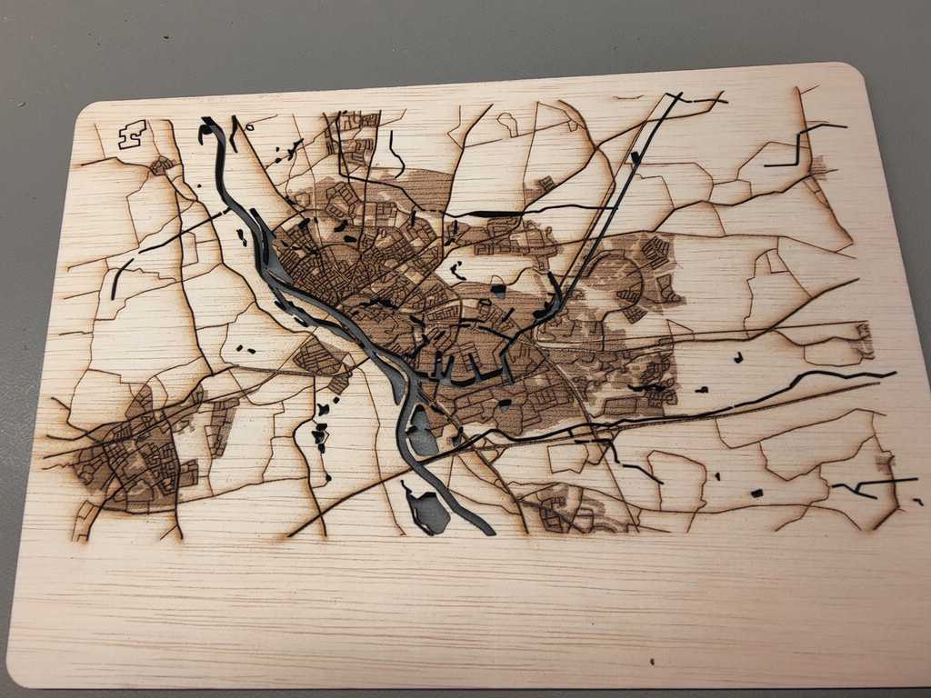
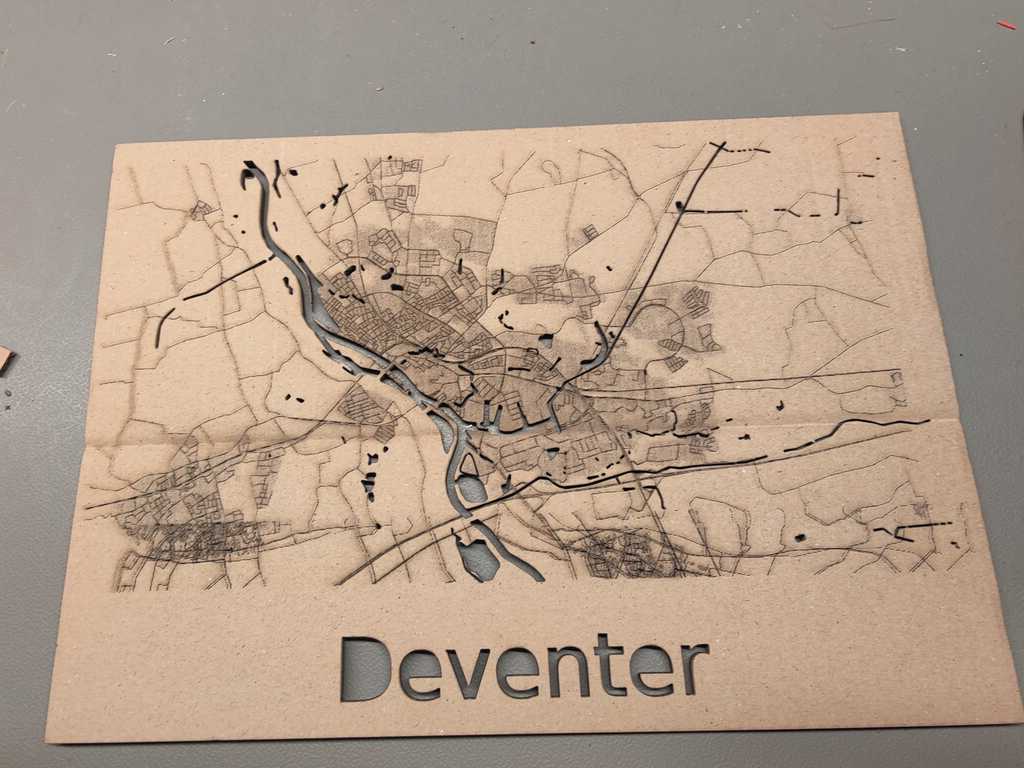
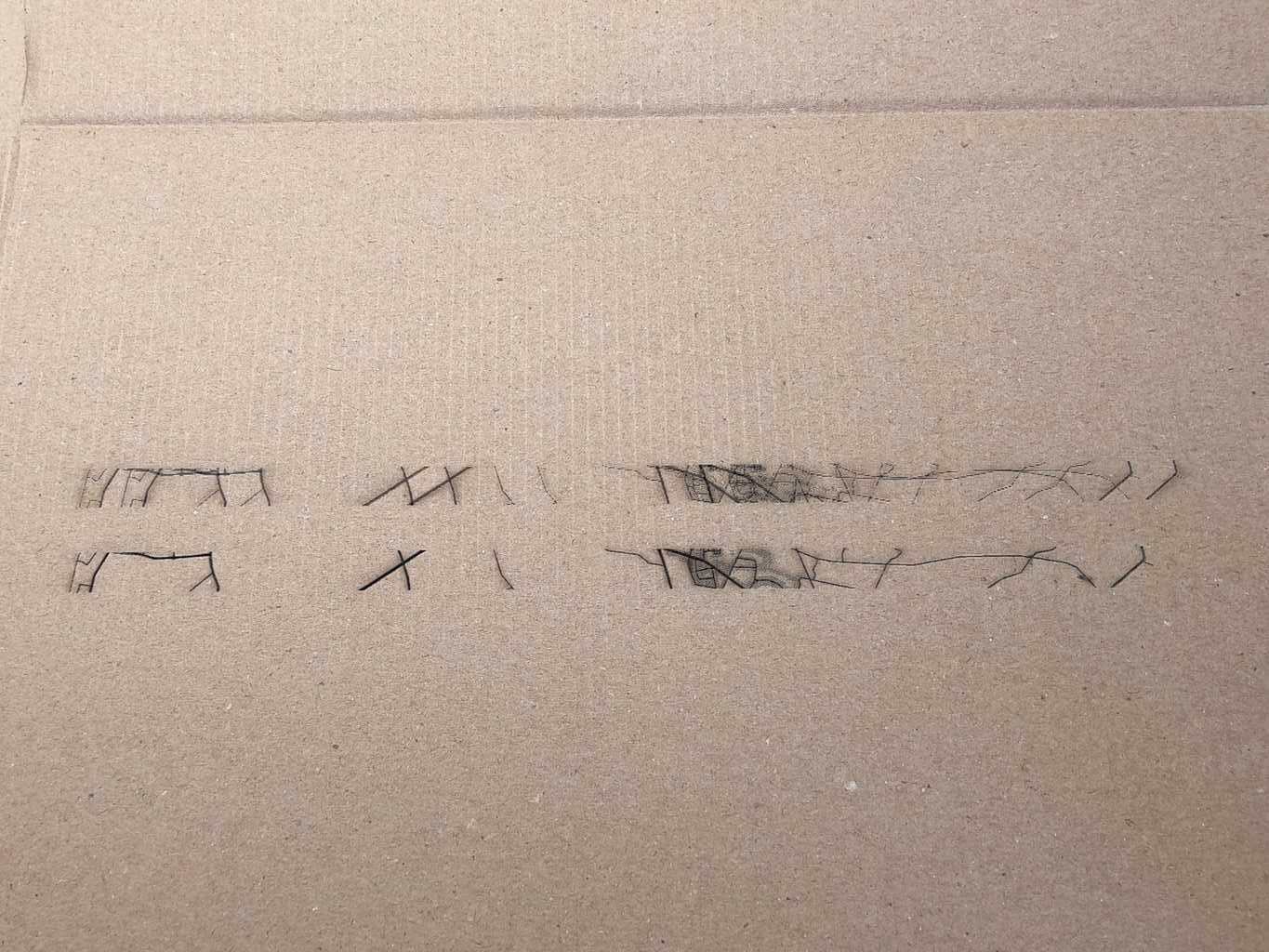
As you can see on the bottom, there is a ghosting of the image. I restarted the job with uni-directional rastering and the ghosting was gone. But the water was cut about 5 mm too far to the right in relation to the rastered image.
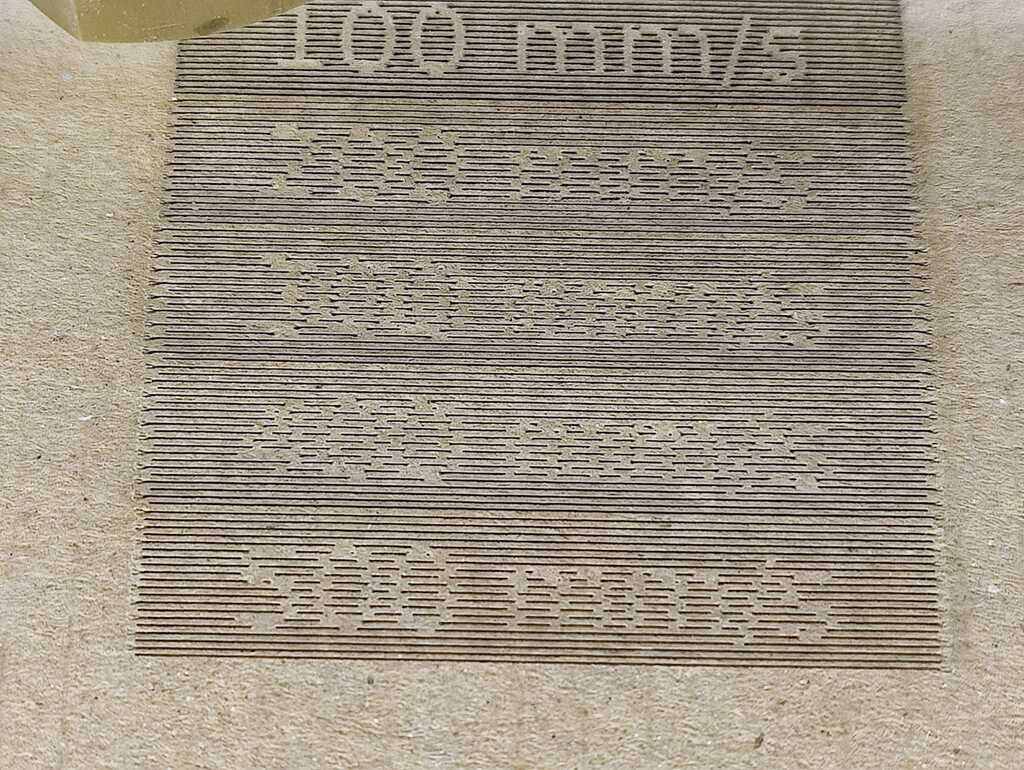
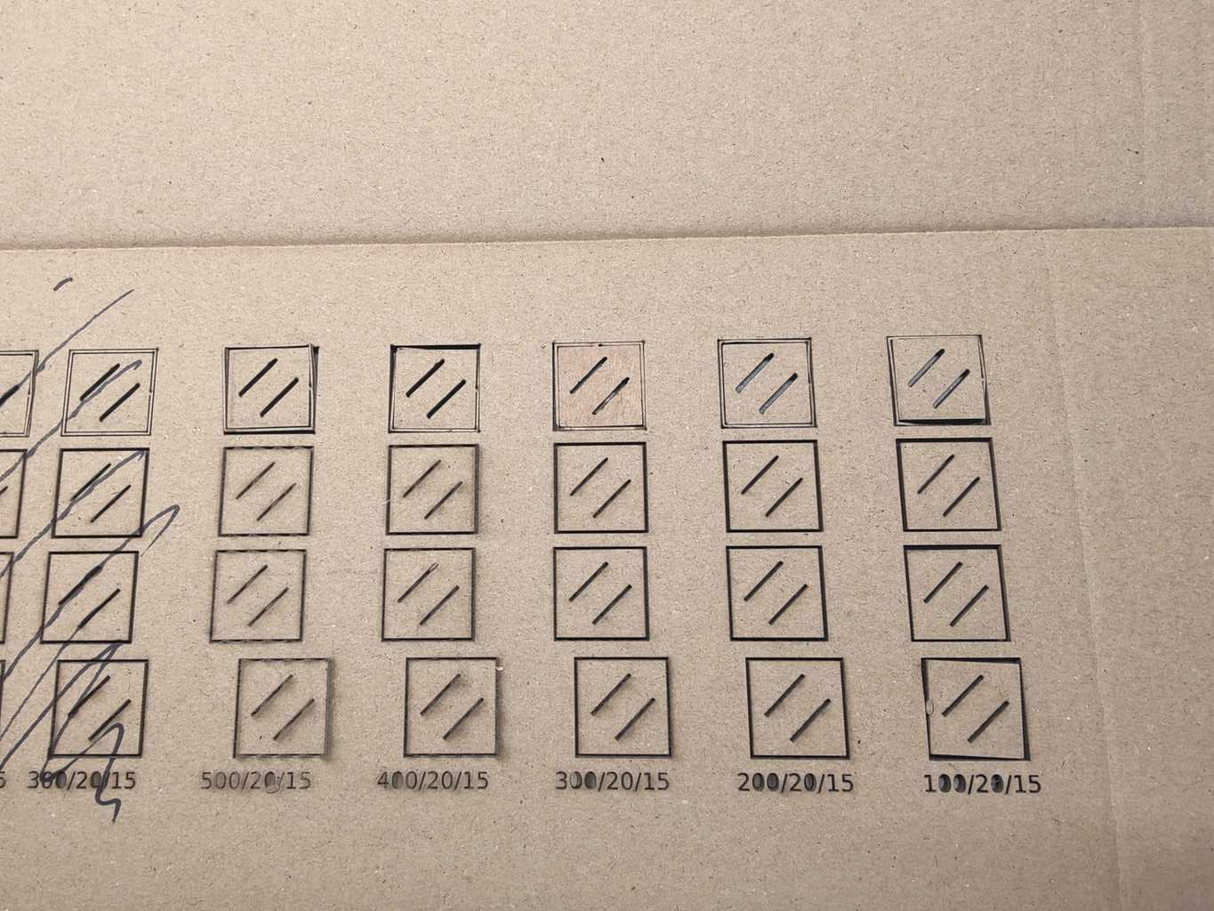
So I created a test-job with an image to test the ghosting and misallignment at various speeds.
The top row is the lightburn-traced image using line
The second row is the lightburn-traced image using fill
The third row is the lightburn-rastered image bi-directional
The fourth row is the lightburn-rastered image uni-directional
The used speeds and powers are engraved at the bottom.
Uni-directional does give a shift (as observed in the city map) but the bi-directional is sharp as a razor!
So I restarted the city map job, but the ghosting is back…